

In the previous section, we learned about the Network Access layer. Essentially we learned more about the anatomy of a frame, physical addressing, and what exactly the physical layer accomplishes. Don’t relax yet- we still have three layers to go!
What the Internet Layer Is Responsible For
The Internet Layer is used to deliver data on a complex routed network. In some cases, we can get by with simply using physical addressing. However, this would only work on extremely small LAN connections that do not use routers. For anything bigger or more complex, we will need to make use of the Internet Layer.
The Internet Layer uses logical addressing, as compared to physical addressing. Logical addresses can be read and forwarded among routers, while physical addresses lack the routed functionality. The Internet Layer is also responsible for identifying computers on any network so that data can be successfully sent. Lastly, the Internet Layer is responsible for converting the logical IP address of the destination computer to a physical address, so data can be delivered to the correct computer.
Don’t worry if this is an information overload- we’ll cover all of these aspects more specifically later on in the section.
The Anatomy of an IP Datagram
Before we get into how the Internet Layer routes data, we first have to know what it is routing exactly. Specifically, data at this level is called a datagram. And from what we learned in previous sections, we know the Internet Layer attaches an IP header onto data. But what does this IP header consist of?
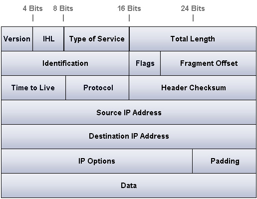
At first glance, this is a lot of information to digest. But don’t be dismayed- it is a lot simpler than you may think. Check below for detailed information on each field.
IP Header Fields Explained
- 1. Version – The version is a binary number that is four bits long. It indicates which version of IP is being used. Currently we are using IP version four, although IP version six will soon make an impact on the networking world.
- 2. IHL (Internet Header Length) – The IHL simply measures the length of the IP header in 32-bit words. The minimum header length is five 32-bit words.
- 3. Type of Service – This field is for specifying special routing information. This field in particular relates to Quality of Service technologies quite well. Essentially, the purpose of this 8-bit field is to prioritize datagrams that are waiting to pass through a router.
- 4. Total Length – This 16-bit field includes the length of the IP datagram. This length includes the IP header and also the data itself.
- 5. Identification – This is a 16-bit field that acts as a means of organizing chunks of data. If a message is too large to fit in one data packet, it is split up and all of its child packets are given the same identification number. This is handy to ensure data is rebuilt on the receiving end properly.
- 6. Flags – This field signifies fragmentation options- such as whether or not fragments are allowed. The Flags field also has capability to tell the receiving source that more fragments are on the way, if enabled. This is done with the MF flag, also known as the more fragments flag.
- 7. Fragment Offset – This is a 13-bit field that assigns a number value to each fragment. The receiving computer will then use these numbers to reassemble the data correctly. Obviously this is only applicable if fragments are allowed.
- 8. Time to Live – This is often known as TTL. It is a field that indicates how many hops a data packet should go through before it is discarded. Every successful pass through a router, known as a hop, decrements this field by one. When it reaches zero, it is discarded.
- 9. Protocol – This 8-bit field indicates which protocol should be used to receive the data. Some of the more popular protocols such as TCP and UDP are identified by the numbers 6 and 17 respectively.
- 10. Header Checksum – This 16-bit field holds a calculated value that is used to verify that the header is still valid. Each time a packet travels through a router this value is recalculated to ensure the header is still indeed valid.
- 11. Destination IP Address – This 32-bit field holds the IP address of the receiving computer. It is used to route the packet and to make sure that only the computer with the IP address in this field obtains the packets.
- 12. Source IP Address – This 32-bit field holds the IP address of the sending computer. It is used to verify correct delivery, and will also be the return address in case an error occurs.
- 13. IP Options – This field can hold a fair number of optional settings. These settings are primarily used for testing and security purposes. Although clever settings such as keeping timestamp data from each router hop may seem handy, it will actually degrade speed more often than not.
- 14. Padding – Since the IP options field varies in length depending on the configuration, we need to have this field set to occupy left over bits. This is because the header needs to be ended after a 32-bit word: no more, no less.
- 15. Data – This is fairly self explanatory- it is simply the data that is being sent.
The above diagram should be reviewed until a firm grasp is held on the concept of an IP header. If you feel you have the concepts down well enough, it’s time to move onto routing the data!
Routing the Information with the IP Protocol and IP Addresses
The Internet Protocol, or IP, operates on the Internet layer. This protocol provides a hardware-independent addressing system in the form of IP addresses. For every Network Interface Card, or NIC, there should be a unique IP address. After all, how could we send data to a specific computer if more than one computer was using an IP address?
Look at the diagram below and see if you can tell any similarities between the IP addresses.
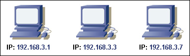
You may have noticed that the first three numbers are identical in each address. IP addresses are made up of two portions: the network ID and the host ID. The network ID is responsible for telling other computers which network the computer resides on (useful if we are using subnets or multiple LAN segments). The host portion tells us which specific computer on the network the computer is. In terms of an actual home address, the network ID would be the street of your home- while the host ID would be the house number.
IP addresses are divided by what are called octets, or simply 8-bit segments. IP addresses also use dotted decimal format: meaning each octet is separated by a period. For every IP address there are four octets. If you do the math right, you will find that each IP address is 32 bits in size (four octets of eight bits each). Refer to the diagram below for more information.
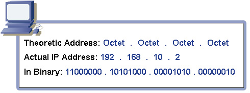
In case you needed proof that each IP address is 32 bits, count each one and zero in the binary format. Each 1 or 0 is a bit. Since there are 8 bits in a byte, we can also say that each IP address is 4 bytes in size.
But we aren’t done yet! Each IP address belongs to a class. You will likely only see three classes on an average basis: Class A, Class B, and Class C. These classes dictate which network type an IP address is. We never actually said which part of the IP address was the network ID and which was the host ID- so how do we know where the network ID starts and where the host ID begins? Classes of course! Review the diagram below for more information.
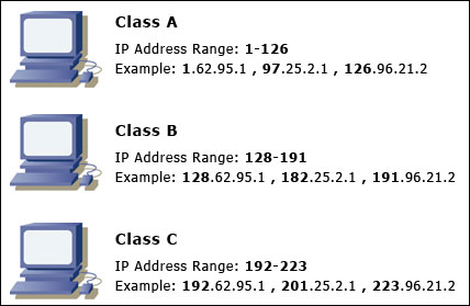
Notice that each class is dictated through the first octet’s value. However, there is more going on behind the scenes that we are aware of with the above diagram. Each class has a specific amount of network and host octets. Review the diagram below for more information.
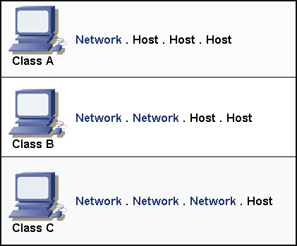
Remembering the network octets is easy- simply remember that each class from A to C adds a network octet. Keep in mind that Class D and Class E addresses exist, but for the sake of simplicity, we will not cover them just yet since you’ll likely not use one anytime soon. For now, we have one more thing to learn about concerning IP addresses: reserved IP addresses.
Reserved IP Addresses
There are certain IP addresses that are reserved; meaning they have a special purpose. For instance, you can’t use all zeroes for the host octets, since this is the actual network address. (The Class C address 192.168.2.0 is not usable, for instance.) We also may not use the broadcast address- which is simply represented as all 1’s in binary, or 255 in decimal. (The Class C address 192.168.2.255 is not usable, for instance.) Don’t worry- we will cover broadcast addresses more thoroughly in later sections. Lastly, you may not use the 127.0.0.1 address since it is a loopback address- mainly used for testing and troubleshooting.
There are certain IP addresses that are used for private networks, meaning that they aren’t for internet use. These addresses, therefore, don’t have to be unique and can be used for network use. These private addresses are:
Reserved IP Addresses
- 1. 10.0.0.0 to 10.255.255.255
- 2. 172.16.0.0 to 172.31.255.255
- 3. 192.168.0.0 to 192.168.255.255
Use these addresses however you see fit on your own network- but also know that since these are private addresses, you may not access the internet with them.
Last but not Least, ARP and RARP
We certainly have covered a lot so far! Don’t worry- we only have ARP and RARP to review for now. The Address Resolution Protocol, or ARP, is used to map IP addresses to physical addresses. To actually deliver data to a computer we use its physical address. You may remember that every physical address is unique and is burned into the NIC card at the factory.
Your Network InterfaceCard is actually a fairly dumb device. All it does when receiving data is look at incoming information and check to see if it is addressed to it or not. Ironically, it doesn’t even know its own IP address! Since we can’t depend on the NIC card we use ARP tables, otherwise known as the ARP cache.
The best part of the situation is that ARP tables are built dynamically- no need to configure anything normally. These ARP tables will associate physical addresses to logical addresses, and will be used to route data to specific computers. But what if there aren’t any addresses in the ARP tables, yet we have data being sent to a computer on a network? In this instance, the host sends a broadcast called an ARP request frame.
The ARP request frame contains IP address and physical address information for the host that sent the request. Other hosts on the network receive the ARP request, and hopefully the unresolved IP address is found out. If it is, a new entry into the ARP table is made. This happens more than you’d think since ARP tables actually expire after a certain amount of time.
Simple enough, right? Next we have RARP, which can be simply seen as the opposite of ARP. It technically stands for Reverse ARP, so you wouldn’t be wrong in believing this. RARP is used when the IP address is known, but the physical address isn’t.
Closing Comments
We certainly got through a lot of information! If you haven’t noticed, the Internet Layer is a lot more complex than the physical layer. In the next section we will take a look at the Transport Layer in particular. It is highly recommended that you read our subnetting article before continuing. If you feel you have a firm grasp on the subnetting concept, you may continue to the next section.
Got a project that needs expert IT support?
From Linux and Microsoft Server to VMware, networking, and more, our team at CR Tech is here to help.
Get personalized support today and ensure your systems are running at peak performance or make sure that your project turns out to be a successful one!
CONTACT US NOW