The Network Access Layer it is the layer responsible for interfacing with your network’s architecture- something the everyday user can’t see. As we can’t physically interact with the Network Access Layer, how it works often eludes networking students.
If you haven’t already, you may wish to read the previous section on encapsulation- we will be reviewing part of the encapsulation again in this section.
What the Network Access Layer Accomplishes
It may be poor for education, but the Network Access Layer’s invisibility to the everyday user means management of the layer is unnecessary in most cases. Inventions such as the Universal Plug and Play (known to early Windows users as “Plug and Pray”) enables users to setup networked devices with little to no configuration.
Behind the scenes, the Network Access Layer is responsible for several things; including error checking, formatting data into frames, and interfacing with network adapters. See the box below for the full list of responsibilities of the Network Access Layer.
Responsibilities of the Network Access Layer
- 1. Checks for errors on incoming frames, and sends error checking information on outgoing frames so receiving computers can check for errors.
- 2. Acknowledgement of received frames is another feature. If a frame isn’t received correctly, it will be resent to the appropriate destination.
- 3. Formats outgoing data into frames, and then converts the data into electrical pulses for transmission. The receiving computer will rebuild the frame, and send the data up to the next layer.
- 4. Interfaces with network adapters and coordinates data transmission with the selected network architecture. An Ethernet network, for instance, will require different transmission methods than a Token Ring network.
Dividing the Network Access Layer with the OSI Model
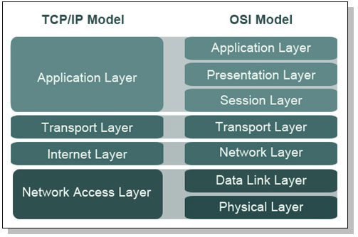
The TCP/IP model only has four layers as compared to the OSI model’s seven. The Network Access Layer in particular is subdivided into two separate layers in the OSI model. Because this aids in learning, we will be working with the OSI model in this section. You can see a visual diagram of the two models below.

We are now dealing with two layers: the Data Link Layer and the Physical Layer. The Physical Layer is the layer responsible for turning the data frame into a stream of bits. This breakdown of the frame into bits is necessary for transmission. On the receiving end, the Physical Layer rebuilds the bits into a frame.
The Data Link Layer actually performs two different functions: Media Access Control, or MAC, and Logical Link Control, or LLC. The Media Access Control is the sublayer that provides an interface with the network adapter, otherwise known as your Network Interface Card or NIC. This card holds your MAC address, which is burned into your Network Interface Card at the factory of which it was made.
The Logical Link Control is the sublayer that performs error checking for frames. It also manages links between devices that are communicating over a subnet. It also offers flow control and acknowledgement of delivery.
Physical Addressing
Physical addressing is the aspect of the Network Access Layer that relates physical addresses to logical addresses. This is nothing more than simply converting your MAC address to an IP address for easier use in management.
Data sent across a network uses the physical address, so why not just use the physical address as compared to a logical address? Among other reasons, the physical address is too lengthy for practical use by humans. In the case of an Ethernet network, it is 48 bits long.
To actually go from a physical address to a logical address (or vice versa), we need to use ARP and RARP. Address Resolution Protocol and Reverse Address Resolution Protocol can relate IP addresses to physical addresses. These protocols function largely on the Internet Layer, so we’ll come back to them in our next section.
Dissecting a Frame of Data
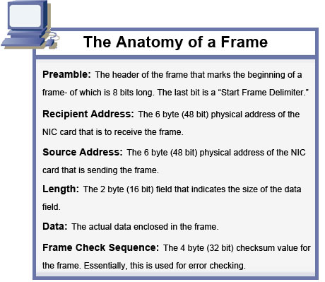
As a short review, we know that the Network Access Layer accepts a datagram from the Internet Layer, creates a frame, and then grinds the frame down into electrical pulses for transmission. But what we haven’t covered is what the frame is exactly- but you’re in luck, there is a handy diagram shown below.

While most of the above fields are self-explanatory, the frame check sequence, or FCS, needs some explanation. This is a means of verifying data transmissions. The sending computer calculates what is called a Cyclical Redundancy Check, or CRS, and sends the calculation with the frame. If the receiving computer performs the CRS calculation and it matches, all the data is present. Otherwise, data was lost in the transmission. Don’t worry if this is confusing to you- we’ll review it more in later chapters.
Also, a good think to take note of is that each frame can only be between 64 bytes and 1,518 bytes in size. This, however, does not include the preamble’s size in the measurement. If the data being sent is larger than this, the information must be broken down into individual frames; of which will be rebuilt at the receiving computer.
Closing Comments
The Network Access Layer accomplishes a lot for being nearly invisible to the everyday computer user. It’s such a large topic, in fact, that we are overjoyed models like the OSI model could split it up into two separate layers.
We now know that the Network Access Layer interfaces with different network types (such as Ethernet or Token Ring configurations), performs error checking via the Frame Check Sequence, and is ultimately responsible for getting information to its destination.
The Network Access Layer is just one layer of the TCP/IP model, however- and in our next section we will be taking a closer look at logical addressing at its finest- the Internet Layer!
Got a project that needs expert IT support?
From Linux and Microsoft Server to VMware, networking, and more, our team at CR Tech is here to help.
Get personalized support today and ensure your systems are running at peak performance or make sure that your project turns out to be a successful one!
CONTACT US NOW

