In the previous section we took a look at the Internet Layer. We took apart the IP header information, reviewed IP addresses and routing information, and briefly discussed ARP and RARP technologies.
Next in line we have the Transport layer- the layer responsible for actually getting the data packets to a specific location. When we receive email, we want to open it with our email program- not anything else. So how does a computer know exactly where to route data to appropriate programs, all while dealing with multiple connections?
The Difference between TCP and UDP
There are two protocols that are primarily used to transport data: TCP and UDP. TCP stands for transmission control protocol. It is the more common of the two, since it allows for much more error checking functionality and stability. UDP, or User Datagram Protocol, lacks extensive error checking- but is considered to be much faster than TCP as a result.
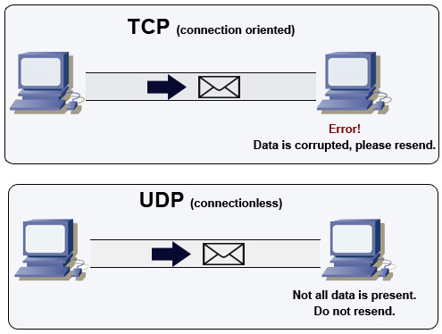
Since TCP guarantees the delivery of data over a network we call it a connection-oriented protocol. If in the event that data isn’t sent correctly, the sending computer will be notified and will resend the information. This is compared to UDP, which doesn’t require that data has been received correctly. Likewise, we call UDP a connectionless protocol.
How Do Transport Protocols Work?
We mentioned earlier that a transport protocol can have simultaneous connections to a computer- yet the receiving computer still knows where each data packet should be sent. This is accomplished through ports and sockets.
A port is simply an internal address that acts as a pathway to control data flow. Since we need each port to be specific to a certain application, there are thousands of ports for use. If you are using the internet, for instance, data is being routed through TCP port 80. This port is called the HTTP port. Ports that have specific purposes (such as the HTTP port) are also known as well-known ports. (And in case you were wondering, there are over 65,535 ports to experiment with.)
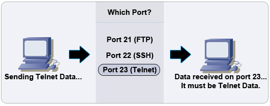
So now we know two things. First, the IP address is used to route the data to a specific computer. Next, the port number is used to tell the receiving computer what kind of application should handle it. But to actually accomplish both of these tasks, we use what is called a socket. A socket is simply an address formed by using the IP address and then tacking on the port number at the end.
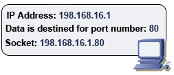
Practical Uses of the Socket
So what good is a socket? For one thing, multiplexing and demultiplexing is made possible. When you are running multiple programs that are communicating with other computers, you are making use of both of these technologies.
Let’s look at a practical example. You are running a telnet server in which multiple computers are connected to. Each computer uses a socket address to tell the server which computer and which port the data is coming from. If each computer broadcasted at the same time, there may be a jam at the transport layer. We use multiplexing in this case to combine all incoming data into one stream.
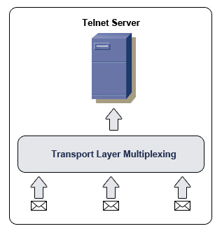
Demultiplexing is very similar to multiplexing, except that it works in reverse. Instead of taking multiple streams of input data and outputting a single stream of data, demultiplexing involves receiving a single stream of input and delivering it to multiple outputs. This is handy for separating multiplexed signals. You may see demultiplexing referred to as “Demuxing.”
The Anatomy of a TCP Segment
So now we know how data is routed, but what is the data made up of? As we learned in previous sections, we call the data at the Transport level of the TCP protocol a segment.
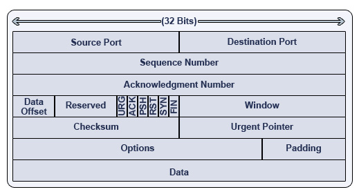
TCP Segments Explained
- 1. Source Port – A 16-bit field that specifies which port number the data segment originated from on the source machine.
- 2. Destination Port – A 16-bit field that specifies which port number the data segment is destined for on the receiving machine.
- 3. Sequence Number – A 32-bit field that specifies which sequence number the particular segment of information is assigned. The sequence number is used to number packets of information so that they may be counted on the receiving side- guaranteeing a successful and complete delivery of information.
- 4. Acknowledgment Number – A 32 bit field that specifies whether or not a segment was received correctly. The acknowledgment number is always one higher than the sequence number, since the receiving computer is expecting the next segment.
- 5. Data Offset – A 4-bit field that tells the receiving computer how long the header is, and where the data actually begins.
- 6. Reserved – A 6-bit field that is reserved for future use. Currently this field is represented as all zeroes. In the future, it may be likely that TCP will make use of this space for some reason or another.
- 7. URG – A 1-bit control flag that stands for urgent. If the value is 1, the information is urgent and should be dealt with accordingly.
- 8. ACK – A 1-bit control flag that, if set to 1, indicates that the Acknowledgment Number field is significant.
- 9. PSH – A 1-bit control flag that stands for push. If set to 1, all the information sent so far is sent to the receiving application.
- 10. RST – 1-bit control flag that stands for reset. If set to 1, the connection is reset.
- 11. SYN – A 1-bit control flag that stands for synchronize. If set to 1, then a sequence of numbers will be used to sort information packets. This also marks the beginning of a connection.
- 12. FIN – A 1-bit control flag that stands for finished. It also closes a connection, and indicates that there is no more data to be sent.
- 13. Window – A 16-bit field that is used for flow control. It indicates that a range of sequence numbers past the last acknowledged sequence number do not require further acknowledgment.
- 14. Checksum – A 16-bit field that checks segment integrity. A calculation is done on both the sending and receiving computer. This calculation is based on the segment’s information, so we can use it to check and see if the packet is indeed the same being received as it was sent.
- 15. Urgent Pointer – A 16-bit field that indicates the beginning of urgent information. Specifically, it points to a sequence number.
- 16. Options – A field that may be used to set various optional settings.
- 17. Padding – A spacer used to offset the Options field. Since every row must equal 32 bits, the Padding field must add to the Options field to equal 32 bits. Since the Options field may vary, variable Padding is needed.
- 18. Data – The actual data being sent to the recipient computer.
The Anatomy of a UDP Datagram
Don’t worry- UDP is a lot simpler as compared to the TCP counterpart. This is due to the lack of error checking UDP contains. Although UDP is famously known for not having error checking, there are slight UDP functionalities that can act as basic error checking procedures.
It’s important to know that the UDP error checking functionalities are quite basic. For instance, the UDP protocol contains functionality for a checksum so that we may check the integrity of data. This field can be turned off, however, so that a faster connection can be had. Also important to note is that UDP uses a fake header (known as a pseudo-header) that contains a destination address, so that we can determine whether or not the packets were sent to the right place. If they are indeed sent to the wrong place, a simple ICMP message may notify the source machine that the source is unreachable.
Keep in mind that even if errors are found within a UDP connection, data will not be retransmitted. So how much different is a UDP datagram from a TCP segment?

UDP Datagrams Explained
- 1. Source Port – An optional 16-bit field that specifies which port the datagram originated from.
- 2. Destination Port – A 16-bit field that specifies which port the datagram should be directed to on the receiving computer.
- 3. Length – A 16-bit field that specifies how long the UDP datagram is. This includes the UDP header and the data being sent. (The value is always at least 8, since the UDP header is eight octets.)
- 4. Checksum – A 16-bit field that operates much like the TCP counterpart. It is considered optional, however.
- 5. Data – The actual data being sent to the recipient computer.
You will notice that the datagram anatomy is much simpler- and that no source or destination information is included. So how does the data know where to go? As we briefly reviewed earlier, UDP uses what is known as a pseudo-header. This header will act as a guide for the datagram, and can determine whether the datagram was delivered to the right address or not.
Closing Comments
Three layers down, one more to go! In the next section we will take a look at the final TCP/IP layer: the Application Layer. We’ll take an in-depth look at just how data goes from datagrams and segments to actual information you can interact with on your computer.
Got a project that needs expert IT support?
From Linux and Microsoft Server to VMware, networking, and more, our team at CR Tech is here to help.
Get personalized support today and ensure your systems are running at peak performance or make sure that your project turns out to be a successful one!
CONTACT US NOW