How the OSI model is used to help applications to communicate across a network.
Suppose that an application needs to be able to communicate across the network. The application developer does not build network drivers into the application, they merely write the application in a way that allows it to make certain calls to the Windows operating system. The manufacturer of the machine’s network adapter provides a driver that also links to Windows, and Windows performs the necessary match ups that allow the application to communicate with the network adapter.
Of course that is just the quick and dirty version. Things are actually quite a bit more complex than that. After all, the network adapter is just a device that is designed to send and receive packets of data. The card itself knows nothing of Windows, the application, or even of the protocols that are being used.
The example that I provided a moment ago implies that there are three layers at work; the application, the operating system, and the physical hardware. While these layers do exist (but not necessarily by those names), they can be subdivided into several more layers.
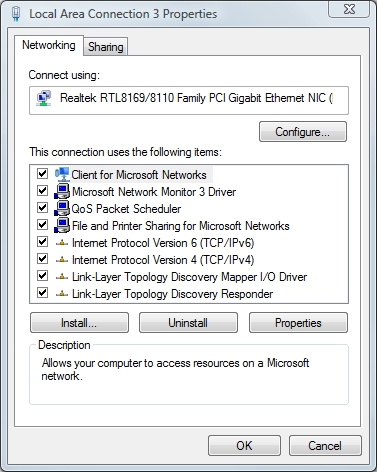
Before I explain what these layers are and what they do, I want to point out that the concepts that I am about to teach you are not abstract. In fact, if you open the Local Area Connection properties sheet, shown in Figure A, you can see that a network connection is made up of several different components, such as the network client, the network adapter driver, and the protocol. Each of these components corresponds to one or more individual layers.

Figure A: The Local Area Connection properties sheet offers a glimpse at the way that the various network layers are implemented in Windows
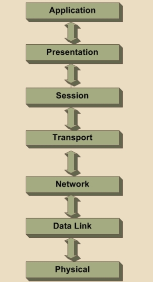
The network model that Windows, and most other network operating systems use is called the OSI Model. The term OSI Model is short for Open System Interconnection Basic Reference Model. The OSI Model consists of seven different layers. Each layer of the model is designed so that it can perform a specific task, and facilitate communications between the layer above it and the layer below it. You can see what the OSI Model looks like in Figure B.

Figure B: The OSI Model
The Application Layer
The top layer of the OSI model is the Application layer. The first thing that you need to understand about the application layer is that it does not refer to the actual applications that users run. Instead, it provides the framework that the actual applications run on top of.
To understand what the application layer does, suppose for a moment that a user wanted to use Internet Explorer to open an FTP session and transfer a file. In this particular case, the application layer would define the file transfer protocol. This protocol is not directly accessible to the end user. The end user must still use an application that is designed to interact with the file transfer protocol. In this case, Internet Explorer would be that application.
The Presentation Layer
The presentation layer does some rather complex things, but everything that the presentation layer does can be summed up in one sentence. The presentation layer takes the data that is provided by the application layer, and converts it into a standard format that the other layers can understand. Likewise, this layer converts the inbound data that is received from the session layer into something that the application layer can understand. The reason why this layer is necessary is because applications handle data differently from one another. In order for network communications to function properly, the data needs to be structured in a standard way.
The Session Layer
Once the data has been put into the correct format, the sending host must establish a session with the receiving host. This is where the session layer comes into play. It is responsible for establishing, maintaining, and eventually terminating the session with the remote host.
The interesting thing about the session layer is that it is more closely related to the application layer than it is to the physical layer. It is easy to think of connecting a network session as being a hardware function, but in actuality, sessions are usually established between applications. If a user is running multiple applications, several of those applications may have established sessions with remote resources at any time.
The Transport Layer
The Transport layer is responsible for maintaining flow control. As you are no doubt aware, the Windows operating system allows users to run multiple applications simultaneously. It is therefore possible that multiple applications, and the operating system itself, may need to communicate over the network simultaneously. The Transport Layer takes the data from each application, and integrates it all into a single stream. This layer is also responsible for providing error checking and performing data recovery when necessary. In essence, the Transport Layer is responsible for ensuring that all of the data makes it from the sending host to the receiving host.
The Network Layer
The Network Layer is responsible for determining how the data will reach the recipient. This layer handles things like addressing, routing, and logical protocols. Since this series is geared toward beginners, I do not want to get too technical, but I will tell you that the Network Layer creates logical paths, known as virtual circuits, between the source and destination hosts. This circuit provides the individual packets with a way to reach their destination. The Network Layer is also responsible for its own error handling, and for packet sequencing and congestion control.
Packet sequencing is necessary because each protocol limits the maximum size of a packet. The amount of data that must be transmitted often exceeds the maximum packet size. Therefore, the data is fragmented into multiple packets. When this happens, the Network Layer assigns each packet a sequence number.
When the data is received by the remote host, that device’s Network layer examines the sequence numbers of the inbound packets, and uses the sequence number to reassemble the data and to figure out if any packets are missing.
If you are having trouble understanding this concept, then imagine that you need to mail a large document to a friend, but do not have a big enough envelope. You could put a few pages into several small envelopes, and then label the envelopes so that your friend knows what order the pages go in. This is exactly the same thing that the Network Layer does.
The Data Link Layer
The data link layer can be sub divided into two other layers; the Media Access Control (MAC) layer, and the Logical Link Control (LLC) layer. The MAC layer basically establishes the computer’s identity on the network, via its MAC address. A MAC address is the address that is assigned to a network adapter at the hardware level. This is the address that is ultimately used when sending and receiving packets. The LLC layer controls frame synchronization and provides a degree of error checking.
The Physical Layer
The physical layer of the OSI model refers to the actual hardware specifications. The Physical Layer defines characteristics such as timing and voltage. The physical layer defines the hardware specifications used by network adapters and by the network cables (assuming that the connection is not wireless). To put it simply, the physical layer defines what it means to transmit and to receive data.
It Works Both Ways
So far I have discussed the OSI Model in terms of an application that needs to transmit data across the network. The OSI Model is also used when a machine receives data. When data is received, that data comes in through the Physical Layer. The remaining layers work to strip away the encapsulation, and put the data into a format that the application layer can use.
In this article, I have explained how Windows uses the OSI model to implement networking. It is important to understand that the OSI model is only a guide as to how networking should be implemented. In the real world, protocol stacks sometimes combine multiple layers into a single component. I will show you how protocol stacks fit into the model in the next article in the series
Got a project that needs expert IT support?
From Linux and Microsoft Server to VMware, networking, and more, our team at CR Tech is here to help.
Get personalized support today and ensure your systems are running at peak performance or make sure that your project turns out to be a successful one!
CONTACT US NOW

